Intel mt-5050 repair

Licence free two-way radio services that now includes both FM and digital channels. Discuss models, modifications and other similar worldwide standards such as FRS and GMRS.
Post Reply
merc07
Regular
Regular
Posts: 6
Joined: 07 Nov 2023, 07:22

Intel mt-5050 repair

Post by merc07 »

Hello,
Are there any resident electronic experts on the forum ?
I have an Intek mt-5050 that someone has been modified by someone to take a removable antenna.
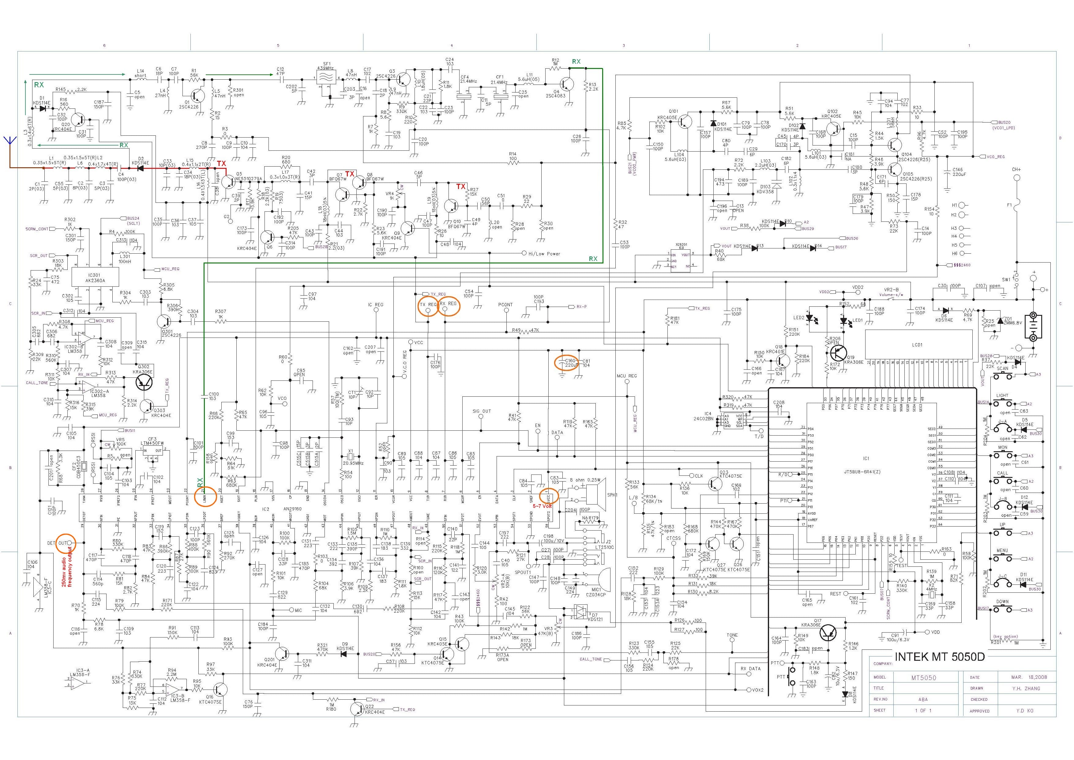
Instead of soldering to the point on the board where the old wire antenna was, they have soldered directly to a surface mount resistor and removed an air core coil inductor.
This must have been deliberate, even if they burned through the track you could still solder to the end of the coil ?
I have another mt-5050 which I added an antenna years back.
Would someone know from the pic what the coil is, I would like to repair it.

No idea how I can upload an image though? {bnghd}

Cheers
merc07
Regular
Regular
Posts: 6
Joined: 07 Nov 2023, 07:22

Re: Intel mt-5050 repair

Post by merc07 »

Could admin grant me permission to add an attachment please, an image of the board with coil, hopefully it can be identified.
It is 5 turns, surface mount, around 2mm in width.

Thanks!
merc07
Regular
Regular
Posts: 6
Joined: 07 Nov 2023, 07:22

Re: Intel mt-5050 repair

Post by merc07 »

Here is another pic from this site, copper coil at the top..
You do not have the required permissions to view the files attached to this post.
merc07
Regular
Regular
Posts: 6
Joined: 07 Nov 2023, 07:22

Re: Intel mt-5050 repair

Post by merc07 »

Posts seem to be disappearing?
Thanks for who ever helped me out with attachments, your post has gone and so has my reply with the image.
Here it is again
You do not have the required permissions to view the files attached to this post.
bitbang
Regular
Regular
Posts: 56
Joined: 18 Oct 2010, 18:00

Re: Intel mt-5050 repair

Post by bitbang »

According to the schematic (if its the correct one!), the coil is 0.35 x 1.5 x 5t and part of the antenna filter
Intek_MT-5050_part_sch.gif
There is some info about the antenna mod here but the pictures are long gone:

http://www.uk-preppers.co.uk/forum/view ... =15&t=1664
You do not have the required permissions to view the files attached to this post.
merc07
Regular
Regular
Posts: 6
Joined: 07 Nov 2023, 07:22

Re: Intel mt-5050 repair

Post by merc07 »

Thanks for this, I was close !

I measured it as 0.4x1.9 and made one over the w/e before I had seen your post.
I'm not sure C1 is connected either, I will have to have another look.
The vswr came down to the same level as my other radio, 1.02-1.5 from around 2.5 to 4.5 so it certainly made a difference there although I have no idea how it would change with the 0.35 wire ?

However the power output still reads very low, 0.5w on low and 0.8w on high (nothing reflected back)- my other reads 1w on low and 4w on high on PMR so there is still something wrong.
LPD channels, read 0.01w on the meter even with the wire clipped to enable more.
I soldered a wire back on to 'C', the power pins and the output is the same - strange ?

I only use them at 0.5w around my home so it doesn't matter too much but would like to get it right if I can.

Is it possible that using it with 2.5 - 4.5vswr in it's previous life has damaged something?
You do not have the required permissions to view the files attached to this post.
bitbang
Regular
Regular
Posts: 56
Joined: 18 Oct 2010, 18:00

Re: Intel mt-5050 repair

Post by bitbang »

That's a good job making that tiny coil! Could have had damage from high power or just a fault, check the RF level at Q5 vs what is at the antenna, follow the TX signal path to see whats not amplifying. Looks like there are two switches for low / high power (Q6 & Q9) controlled by the microprocessor, assume both should have 0v at the base if its on high power.
The horrible schematic is here in case you dont have it, https://cbtricks.org/radios/intek/mt505 ... 50-Sch.jpg
merc07
Regular
Regular
Posts: 6
Joined: 07 Nov 2023, 07:22

Re: Intel mt-5050 repair

Post by merc07 »

Thanks for the diagram, very helpful.

C1 was not connected to L1, I joined them and the power has now risen slightly to a more acceptable level.
Low power is what it should be at so I am happy with that.

I have ordered some 0.35 wire, this will be a couple of weeks - probably not until December.
I may try that but, will see how it goes.. :D
Post Reply