

first off i'd like to thank Dragonfly for all his help with this item, he found the only information i have seen so far on this unit.
So i'd like to get it working, i should possibly say working correctly as it does seem to do something however it's not exactly fully functioning
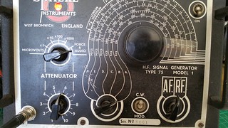
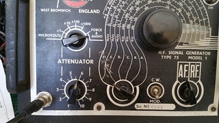
The unit has a date of around 1949 according to the info Dragonfly found, so it uses valves!
These appear to be working and light up, much more than that i don't know about those.
So when opperated it appears to put out a signal only when set to the force and audio position on the MicroVolt switch.
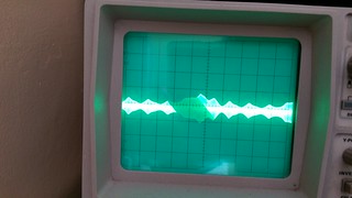
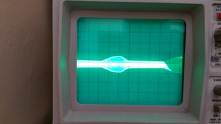
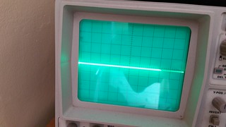
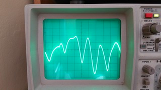
The scope patterns are poor, you can seen some sort of modulated signal, you can attenuate the signal aswell as adjust the frequency on the display.
this is when it is set on RF, you patterns like like those seen from a modulated signal if you monitored a transmission with a scope.
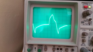
On Af you get a wave form of sorts but it is very messy, you can vary it to some degree on the scope.
On the frequency counter not much unless on force and audio then it is nowhere near the frequency on the dial.
On Rf set to around 27.500 MHz you can eventually find the signal produced by the Rf generator on a Rig the signal moves the needle maybe 3db with some hiss but no tone can be heard.
My guess is the capacitors are probably duff but i don't have any replacements or any way of testing the valves.
I have no Circuit diagram i am hoping that all these Sig Gens of this time period are similar?
So any ideas or input welcomed, i will add some pictures to try and illustrate what i am seeing incase it helps
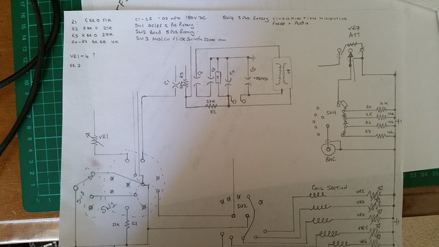
I've started drawing a basic circuit diagram of what i can see and it is here
Here we are set to Force and Audio rf modulated signal.
Here it's set to Rf CW and force and audio
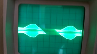
Here the attenuator has been turned up and the signal reads bigger
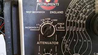
MicroVolts x1000 setting
Here we are set to Af Force and audio Modulated
Af Cw with force and Audio
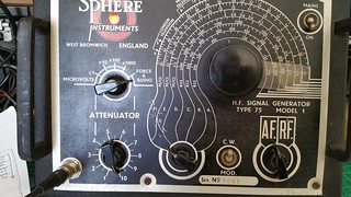
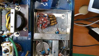
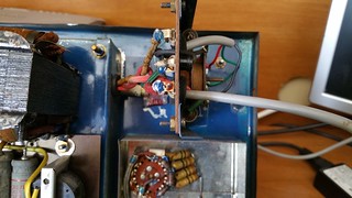
A look inside the Sphere...
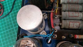
caps and transformer board
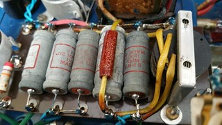
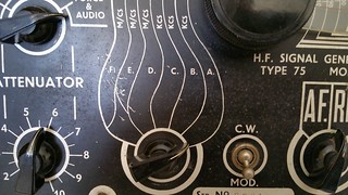
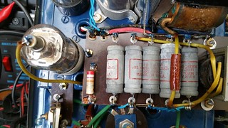
Rear of the Microvolt switch im guessing somekind of diode on the resistor pack but what is the white thing at the top?
Large cap
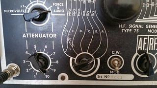
The Switches as per diagram Rf/Af, CW/Mod and Band

Attenuator switch
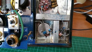
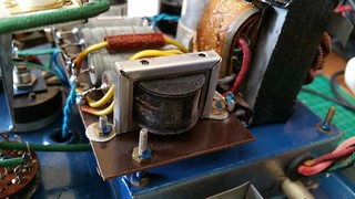
Mains Transformer
Tansformer and Valve 1
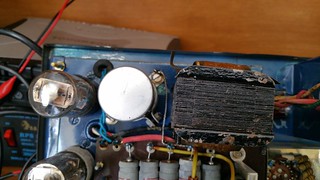
Valve 2
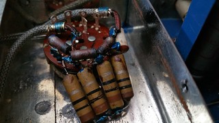
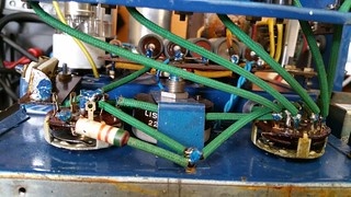
The Frequency coils
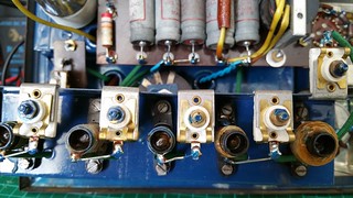
im guessing those white adjusters are some sort of variable resistor?
Thanks
Sean

