Hi friends, HNY!
Just got a JFK in where the ASC is not working. Preowner has activated Roger Beep at the Power adjustment. If Roger Beep is enabled, squelch does not work. So i am looking for schematic for the Uniden PA-338AC JFK with ASC.
Thanks and 73s,
Ralf
President JFK ASC module wiring
-
13EL121

- Radio Addict

- Posts: 618
- Joined: 16 Sep 2008, 20:55
- Call Sign: 13DA121
- Location: Germany
- Contact:
-
14CS06

- Top Poster

- Posts: 1796
- Joined: 04 Mar 2012, 09:15
- Location: JN33LN - ALPES-MARITIMES-06 France
Re: President JFK ASC module wiring
Hello Ralf
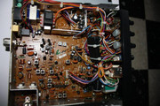
Please look at these pics for JFK and JFK ASC
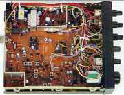
Mods for make independent Beep and ASC
Sorry in french
Schematic without ASC
@+
Claude
Please look at these pics for JFK and JFK ASC
Mods for make independent Beep and ASC
Sorry in french
Schematic without ASC
@+
Claude
Photo Collector CB RADIO
-
13EL121
- Radio Addict
- Posts: 618
- Joined: 16 Sep 2008, 20:55
- Call Sign: 13DA121
- Location: Germany
- Contact:
Re: President JFK ASC module wiring
-
13EL121
- Radio Addict
- Posts: 618
- Joined: 16 Sep 2008, 20:55
- Call Sign: 13DA121
- Location: Germany
- Contact:
Re: President JFK ASC module wiring
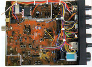
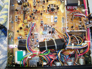
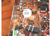
The wire colours seem to be different here. What a mess...
ASC wiring here:
Orange and yellow are not used in mine. Brown and black are grounded together to volume switch. Green goes to the pull switch. Red goes to 8v, blue to a resistor to PCB.
ASC wiring here:
Orange and yellow are not used in mine. Brown and black are grounded together to volume switch. Green goes to the pull switch. Red goes to 8v, blue to a resistor to PCB.
You do not have the required permissions to view the files attached to this post.
-
14CS06
- Top Poster
- Posts: 1796
- Joined: 04 Mar 2012, 09:15
- Location: JN33LN - ALPES-MARITIMES-06 France
-
13EL121
- Radio Addict
- Posts: 618
- Joined: 16 Sep 2008, 20:55
- Call Sign: 13DA121
- Location: Germany
- Contact:
Re: President JFK ASC module wiring
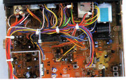
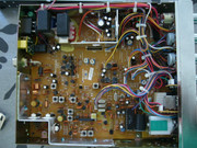
Many thanks Claude! The wireing looks good so far. A picture from the soldering side would be great. I only see one from the JFK Classic without ASC. In mine there are a red and orange wire soldered together to one solder point.
-
14CS06
- Top Poster
- Posts: 1796
- Joined: 04 Mar 2012, 09:15
- Location: JN33LN - ALPES-MARITIMES-06 France
Re: President JFK ASC module wiring
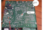
Photo Collector CB RADIO
-
13EL121
- Radio Addict
- Posts: 618
- Joined: 16 Sep 2008, 20:55
- Call Sign: 13DA121
- Location: Germany
- Contact:
Re: President JFK ASC module wiring
Perfect Claude! 
But it looks like mine. Can not see any difference in the section where both cables are soldered together. Hmmm...so i think the magic is the pull switch.
But it looks like mine. Can not see any difference in the section where both cables are soldered together. Hmmm...so i think the magic is the pull switch.
-
13EL121
- Radio Addict
- Posts: 618
- Joined: 16 Sep 2008, 20:55
- Call Sign: 13DA121
- Location: Germany
- Contact:
Re: President JFK ASC module wiring
Fixed...i removed the ASC module as i did not found the fault. Resoldered the tracks and squelch wire. Finally i removed the ASC Stickers and added a 1000uf capacitor for better voltage filtering. Now it is a JFK without ASC and working fine. Roger Beep and Squelch now working as it should. Thanks for your help my friend Claude.
You do not have the required permissions to view the files attached to this post.
-
Crusader

- Veteran

- Posts: 2827
- Joined: 27 Nov 2008, 23:43
- Location: South Cumberland
Re: President JFK ASC module wiring
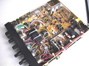
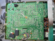
Hi guys, i have a ASC JFK here & the blue wired from it with the resistor has come loose & i need to know where it fixes to so that i can resolder it back in to position.
I can see by the pictures on here it attaches somewhere near the front end of the pcb near the oblong black 455khz ceramic filter, but i cannot see exactly where it attaches.
I can see by the pictures on here it attaches somewhere near the front end of the pcb near the oblong black 455khz ceramic filter, but i cannot see exactly where it attaches.
-
13EL121
- Radio Addict
- Posts: 618
- Joined: 16 Sep 2008, 20:55
- Call Sign: 13DA121
- Location: Germany
- Contact:
Re: President JFK ASC module wiring
Hope this helps...
You do not have the required permissions to view the files attached to this post.
-
13EL121
- Radio Addict
- Posts: 618
- Joined: 16 Sep 2008, 20:55
- Call Sign: 13DA121
- Location: Germany
- Contact:
Re: President JFK ASC module wiring
Soldered on the top end of the resistor.
You do not have the required permissions to view the files attached to this post.
-
Crusader
- Veteran
- Posts: 2827
- Joined: 27 Nov 2008, 23:43
- Location: South Cumberland
Re: President JFK ASC module wiring
Hi,sorry for the delay in me replying & thank you for the pictures, yes i realised the blue wire attached to the resistor, i just wanted to know where the resistor soldered to? by the looks of it to the resistor next to D5.
Best 73, Shaun
-
14CS06
- Top Poster
- Posts: 1796
- Joined: 04 Mar 2012, 09:15
- Location: JN33LN - ALPES-MARITIMES-06 France
Re: President JFK ASC module wiring
Hello
here
@+
Claude
here
@+
Claude
You do not have the required permissions to view the files attached to this post.
Photo Collector CB RADIO
-
Crusader
- Veteran
- Posts: 2827
- Joined: 27 Nov 2008, 23:43
- Location: South Cumberland