Hi,
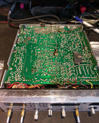
I've got a President Ronald (EPT360011Z PCB) that under a certain condition fails to change frequency (stuck around 27.971 MHz) or transmit when switched to the "Lo" bands; however, on the "Hi" bands it appears to function normally. Based on a few T1 posts I found on here, I believe I have a President Ronald 1 as the PCB version is EPT360011Z and it's 6 band.
Superstar 3900 (High Band) 25615-28305 P1.jpg
I attempted carrying out a full alignment, as per the French version of the service manual and a little of the Secret CB Superstar 3900 (Hi Band) alignment procedure, to see if somehow the PLL was out of lock for the low bands but I initially hit a problem when trying to confirm AM, Band A, Channel 7 is 2.0V (TP2, R109). Secret CB advises the check is 2.2V on Channel 1, but this doesn't change the result. The voltage I get is over 8V on Bands A to C, on any channel even though I've successfully set the radio via L17 to 5.0V on Band F, channel 40, as per the service manual. As I say, the Hi bands, D to F, appear to be responding normally to band and channel changes, though I've not carried out a full channel-to-frequency check yet.
Anyway, I had the radio turned off overnight and returned to it to continue to troubleshoot. On turning on, the low band channels and complete function, including transmit, were working

So, I tried to continue with the alignment and found I was able to confirm 2.0V (TP2 R109) on AM, Band A, channel 7 and roughly 2.2V on channel 1 (Secret CB procedure). So far, so good. So then I go to the next step, which is to connect the FC to TP3 (R74); set AM Clarifier centred, Band C, Channel 19; and then adjust "A" to obtain 16.040 MHz 9 (according to Secret CB). This setting appears to be quite off and drifting rapidly between 16.04746 and 16.04755 MHz so I bring it back down to 16.040 MHz, but its still bouncing around this frequency. I then switch to USB for the next step and that's when the frequency counter jumps to 17.27995 MHz and stays thereabouts no matter where the mode switch is set. The radio's frequency counter is then back showing around 27.971 MHz and changes only the last digit, plus or minus a few kHz, up or down, but not stably or consistently. I then switch the radio off and on - no change - then off for an hour to let it cool down. Switching it back on restores a functioning low band setting again. Looking at the FC I can see that the 16.040 MHz I set earlier has jumped to over 16.042 MHz and rapidly drifting up to around roughly +/- 500 Hz. Leaving the radio to warm up, it drifts down to about 16.0385 MHz, so I bring it back up to 16.040 MHz, or thereabouts as it jumps and falls up to around +/- 300 Hz. Then, switching from AM to USB causes the problem all over again and the FC to show 17.27995 MHz (TP3, R74) and the on-board FC to show 27.971 MHz. By the way, the radio will receive on 27.971 MHz, just not change with the channel selector. It'll change a little, as I mentioned, but seemingly randomly by just a +/- 1kHz, so I can still here my mod tone for instance.
I'm guessing I may have a problem with the 14.010 MHz xtal but would appreciate some expert advice on this if possibe?
Cheers
You do not have the required permissions to view the files attached to this post.