Finally stopped the Galaxy / ranger drifting
Posted: 11 Oct 2018, 12:23
Haven't posted much or done anything in the way of experimentation / modifications over the last year or two due to changed work commitments.
We had one person retire and another one leave for family reasons, and the changing nature of work to shorter term contracts meant we were not willing to replace them with people that we couldn't guarantee a long term position. Because of this I went from office / admin to more hands on work here. After 18 months it's starting to slow down a bit, giving me time to play.
There are two main types of requests we've been getting over the last year and a bit, so we tackled these first, hopefully with one solution to suit both cases. The first was curing the bad drifting issue that the "ten meter export" type radios all suffer from to some degree. The second was converting some older non-PLL 23 channel radios to cover at least the standard 40 channels. Whatever we came up with would ideally do both jobs using the same hardware.
The latter also had a couple of "would be nice if it could do this" requests.
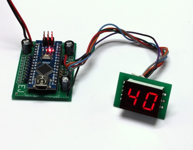
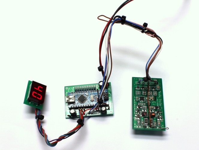
The first was a traditional 2 digit LED display to replace dial readouts, and the second was PC control so a standalone radio would be stock 40 channels, but expanded mode when controlled by a laptop PC, with things like continuous tuning, scanning, and a spectrum display. That will come later. For now, we just allowed for these features in the design.
The circuit and changes had to use conventional / accepted electronic theory, using parts currently available new from well known suppliers.
So no ground off IC numbers, changing electrolytics for tantalums for more smoother rounded super sliding, whack attacks, NBC1C, pink wire on bottom, or similar nonsense.
First up, the Galaxy / Ranger drift issue. A completely drift free radio is impossible, even if it's only some tiny fraction of a hertz. So the goal is actually "drift reduction", not elimination. To work out how much is acceptable, we used our best Agilent signal generator, modulated with various speech audio, and had 3 people listen to it on a Barrett 2050 SSB receiver. The Agilent is locked to a 10MHz rubidium standard, good for 1Hz steps, and the Barrett is TCXO stable to within 1Hz at the test frequency. By switching between two frequencies without telling the listeners, we found that 15Hz was just detectable by one person and the other two managed 25. My ears were somewhere in the middle, close to 20 Hz.
We had previously measured the temperature inside a car while working on something else a few years back. Coldest was 0 degrees C overnight in Tasmania, hottest was over 50 degrees C here in Sydney during summer.
So we settled for a worst case frequency error of 10Hz over a temperature range of -10 to 60 degrees C (14 to 140 degrees Fahrenheit). Maximum cost of parts AU$100 (US$70, €60, £50). If we could achieve that I'd consider it "cured". Challenge on...
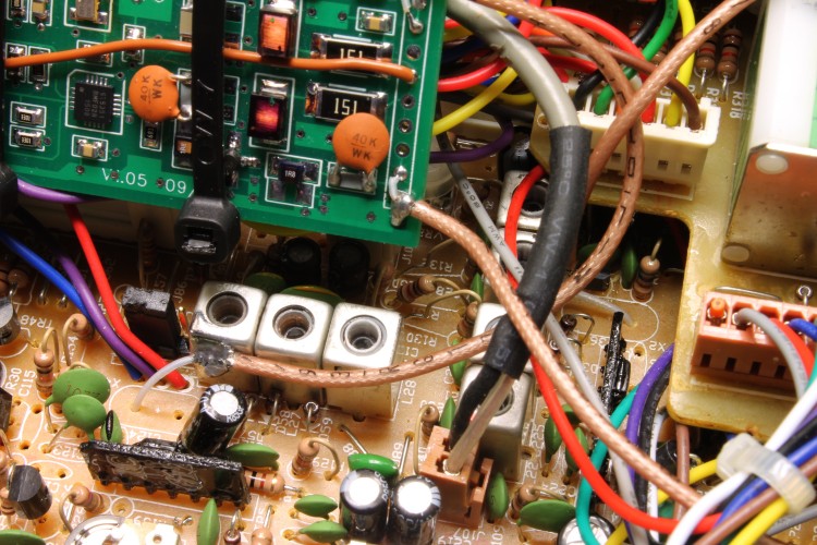
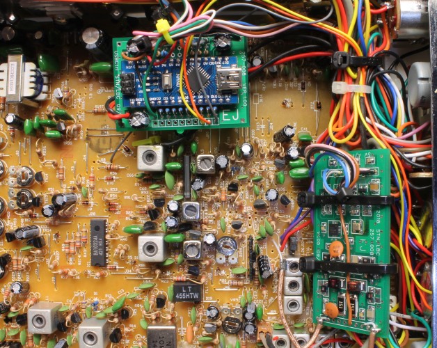
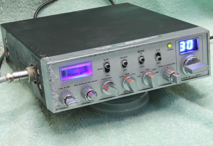
Loz donated a radio to the cause. Virgin late model Superstar 3900, and drifted by nearly 1KHz after being set perfectly a week before. PCB says it's a Ranger. Perfect candidate for this conversion / improvement.
First, know the enemy. Find out why these things drift so badly and which components are the culprits.
The 10.240 MHz oscillator. Generates the 10KHz channel steps, so if its too high the higher channels will be too high and the lower channels too low. The reverse applies if it's too low. In the donor radio it was low but varied only marginally with temperature.
The components in red affect the frequency. By reducing the 30pF capacitor to 27pF we could set it spot on, measured at the 5.12Mhz output pin of the PLL so we wouldn't load down the oscillator. It varied by only a few Hz between cold and hot, so we left this part of the circuit as-is for now at least.
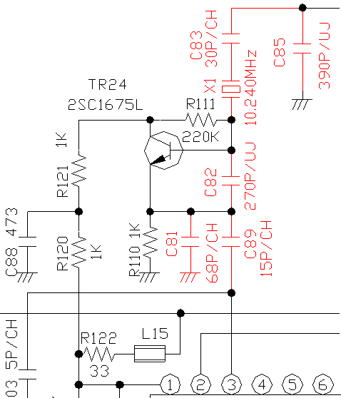
The 10.240 MHz oscillator circuit
Next is the carrier insertion oscillator (CIO). This needs to operate on two or three different frequencies (the 3900 we had uses three) depending on the operating mode. For AM transmission, it operates at 10.695 MHz, which passes through the crystal filter and mixes with the 16 MHz local oscillator to produce the 27MHz transmit signal which is then high level modulated. It must be disabled for AM reception, otherwise it would swamp any incoming signals passing through the first IF stage.
For SSB, it has to be at the edge of the IF filter passband in both Rx and Tx to pass one sideband and reject the other. By putting the signal at the low or high end of the passband, the desired sideband can be selected. For our 3900, the oscillator needs to run at 10.6925 MHz for upper sideband operation and 10.6975 MHz for lower. 3 tunable inductors and capacitors connected from one side of each inductor to ground are used to set the frequency. Those components, plus the crystal and the two phase shifting capacitors in the oscillator are all temperature sensitive (the components shown in red below).
How much by? By using a hot air pencil set to minimum and a can of Freon spray we were able to shift the RF frequency by just over 1KHz by heating and cooling those parts.
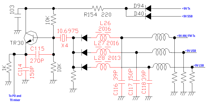
The 10.695 MHz oscillator circuit
Last is the downmix oscillator. This mixes with the VCO / local oscillator (LO) to generate the downmix signal sent to the PLL. No division or multiplication occurs in this stage, so the relationship between the two is 1:1. In other words, if this oscillator is out by 1KHz then the local oscillator will be out be this amount too.
For the "mid" band channel 40 (27.405 MHz), the PLL divides by 270. The IF is 10.695, so the local oscillator frequency must be 16.71 MHz (27.405 - 10.695). 10 KHz x 270 = 2.7 MHz, so a downmix oscillator at 14.010 MHz is needed (16.71 - 2.70 MHz).
For SSB, the frequency has to be offset by half the bandwidth of the filter used to remove the unwanted sideband to cancel out the shift in the carrier oscillator. It therefore has to be shifted down by 2.5KHz for lower sideband and shifted up by 2.5KHz for upper sideband. This keeps the CIO + LO = transmitted frequency math correct. The clarifier is also wired to vary the downmix oscillator up and down by a few KHz, using a varactor diode to change the capacitance across the crystal. Too much capacitance can stop the oscillator, so where lots of range is needed (such as our 3900 with dual clarifiers) an inductance is added to the ground side of the varactor. This increases the range of the clarifier frequency change at the expense of thermal stability.
How much by? By using a hot air pencil set to minimum and a can of Freon spray again, we were able to shift the RF frequency by nearly 10KHz by heating and cooling those parts. Wow. No wonder it was so drifty
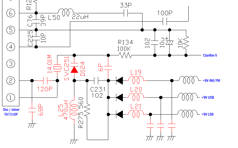
The downmix oscillator circuit. All of the parts in red are temperature sensitive
<continued below>
We had one person retire and another one leave for family reasons, and the changing nature of work to shorter term contracts meant we were not willing to replace them with people that we couldn't guarantee a long term position. Because of this I went from office / admin to more hands on work here. After 18 months it's starting to slow down a bit, giving me time to play.
There are two main types of requests we've been getting over the last year and a bit, so we tackled these first, hopefully with one solution to suit both cases. The first was curing the bad drifting issue that the "ten meter export" type radios all suffer from to some degree. The second was converting some older non-PLL 23 channel radios to cover at least the standard 40 channels. Whatever we came up with would ideally do both jobs using the same hardware.
The latter also had a couple of "would be nice if it could do this" requests.
The first was a traditional 2 digit LED display to replace dial readouts, and the second was PC control so a standalone radio would be stock 40 channels, but expanded mode when controlled by a laptop PC, with things like continuous tuning, scanning, and a spectrum display. That will come later. For now, we just allowed for these features in the design.
The circuit and changes had to use conventional / accepted electronic theory, using parts currently available new from well known suppliers.
So no ground off IC numbers, changing electrolytics for tantalums for more smoother rounded super sliding, whack attacks, NBC1C, pink wire on bottom, or similar nonsense.
First up, the Galaxy / Ranger drift issue. A completely drift free radio is impossible, even if it's only some tiny fraction of a hertz. So the goal is actually "drift reduction", not elimination. To work out how much is acceptable, we used our best Agilent signal generator, modulated with various speech audio, and had 3 people listen to it on a Barrett 2050 SSB receiver. The Agilent is locked to a 10MHz rubidium standard, good for 1Hz steps, and the Barrett is TCXO stable to within 1Hz at the test frequency. By switching between two frequencies without telling the listeners, we found that 15Hz was just detectable by one person and the other two managed 25. My ears were somewhere in the middle, close to 20 Hz.
We had previously measured the temperature inside a car while working on something else a few years back. Coldest was 0 degrees C overnight in Tasmania, hottest was over 50 degrees C here in Sydney during summer.
So we settled for a worst case frequency error of 10Hz over a temperature range of -10 to 60 degrees C (14 to 140 degrees Fahrenheit). Maximum cost of parts AU$100 (US$70, €60, £50). If we could achieve that I'd consider it "cured". Challenge on...
Loz donated a radio to the cause. Virgin late model Superstar 3900, and drifted by nearly 1KHz after being set perfectly a week before. PCB says it's a Ranger. Perfect candidate for this conversion / improvement.
First, know the enemy. Find out why these things drift so badly and which components are the culprits.
The 10.240 MHz oscillator. Generates the 10KHz channel steps, so if its too high the higher channels will be too high and the lower channels too low. The reverse applies if it's too low. In the donor radio it was low but varied only marginally with temperature.
The components in red affect the frequency. By reducing the 30pF capacitor to 27pF we could set it spot on, measured at the 5.12Mhz output pin of the PLL so we wouldn't load down the oscillator. It varied by only a few Hz between cold and hot, so we left this part of the circuit as-is for now at least.
The 10.240 MHz oscillator circuit
Next is the carrier insertion oscillator (CIO). This needs to operate on two or three different frequencies (the 3900 we had uses three) depending on the operating mode. For AM transmission, it operates at 10.695 MHz, which passes through the crystal filter and mixes with the 16 MHz local oscillator to produce the 27MHz transmit signal which is then high level modulated. It must be disabled for AM reception, otherwise it would swamp any incoming signals passing through the first IF stage.
For SSB, it has to be at the edge of the IF filter passband in both Rx and Tx to pass one sideband and reject the other. By putting the signal at the low or high end of the passband, the desired sideband can be selected. For our 3900, the oscillator needs to run at 10.6925 MHz for upper sideband operation and 10.6975 MHz for lower. 3 tunable inductors and capacitors connected from one side of each inductor to ground are used to set the frequency. Those components, plus the crystal and the two phase shifting capacitors in the oscillator are all temperature sensitive (the components shown in red below).
How much by? By using a hot air pencil set to minimum and a can of Freon spray we were able to shift the RF frequency by just over 1KHz by heating and cooling those parts.
The 10.695 MHz oscillator circuit
Last is the downmix oscillator. This mixes with the VCO / local oscillator (LO) to generate the downmix signal sent to the PLL. No division or multiplication occurs in this stage, so the relationship between the two is 1:1. In other words, if this oscillator is out by 1KHz then the local oscillator will be out be this amount too.
For the "mid" band channel 40 (27.405 MHz), the PLL divides by 270. The IF is 10.695, so the local oscillator frequency must be 16.71 MHz (27.405 - 10.695). 10 KHz x 270 = 2.7 MHz, so a downmix oscillator at 14.010 MHz is needed (16.71 - 2.70 MHz).
For SSB, the frequency has to be offset by half the bandwidth of the filter used to remove the unwanted sideband to cancel out the shift in the carrier oscillator. It therefore has to be shifted down by 2.5KHz for lower sideband and shifted up by 2.5KHz for upper sideband. This keeps the CIO + LO = transmitted frequency math correct. The clarifier is also wired to vary the downmix oscillator up and down by a few KHz, using a varactor diode to change the capacitance across the crystal. Too much capacitance can stop the oscillator, so where lots of range is needed (such as our 3900 with dual clarifiers) an inductance is added to the ground side of the varactor. This increases the range of the clarifier frequency change at the expense of thermal stability.
How much by? By using a hot air pencil set to minimum and a can of Freon spray again, we were able to shift the RF frequency by nearly 10KHz by heating and cooling those parts. Wow. No wonder it was so drifty
The downmix oscillator circuit. All of the parts in red are temperature sensitive
<continued below>