Astatic 575-M6 Teardrop.
-
Tim
- Top Poster

- Posts: 1415
- Joined: 10 Jun 2016, 12:35
- Call Sign: 26AT239
- Location: Democratic Republic of Dartmoor
Astatic 575-M6 Teardrop.
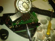
Picked up a tatty teardrop at a local rally yesterday and it's in need of a bit of TLC. The battery connector was rather corroded and the earth wire had parted company with it, new connector fitted. There is another wire that's floating on one end, this is one of the element wires which has parted company from the circuit board, it's pale green, the other, which is still attached is a dark blue wire. There is no evidence where this pale green wire goes onto the board, I've looked at another to compare but this one has a creamy coloured board whereas my other has a green board which is totally different. Can anyone tell me or show me where this wire solders on the board to please? I can put up a picture or two if required.
-
14CS06

- Top Poster
- Posts: 1796
- Joined: 04 Mar 2012, 09:15
- Location: JN33LN - ALPES-MARITIMES-06 France
Re: Astatic 575-M6 Teardrop.
Hello
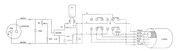
Please llok at this link for schematic
https://lx2smlx2ooo.files.wordpress.com ... _575m6.pdf
@+
Claude
Please llok at this link for schematic
https://lx2smlx2ooo.files.wordpress.com ... _575m6.pdf
@+
Claude
Photo Collector CB RADIO
-
Tim
- Top Poster
- Posts: 1415
- Joined: 10 Jun 2016, 12:35
- Call Sign: 26AT239
- Location: Democratic Republic of Dartmoor
Re: Astatic 575-M6 Teardrop.
Thank you Claude for the schematic but I'm afraid it means very little to me.
Here is a picture of the board, it's that I'm looking at to figure out where the green wire solders on to.
Here is a picture of the board, it's that I'm looking at to figure out where the green wire solders on to.
You do not have the required permissions to view the files attached to this post.
-
14CS06
- Top Poster
- Posts: 1796
- Joined: 04 Mar 2012, 09:15
- Location: JN33LN - ALPES-MARITIMES-06 France
Re: Astatic 575-M6 Teardrop.
Hello
Sorry my Astatic 575-M6 is not the same
@+
Claude
Sorry my Astatic 575-M6 is not the same
@+
Claude
Last edited by 14CS06 on 13 Apr 2018, 17:09, edited 1 time in total.
Photo Collector CB RADIO
-
speeddemon
Re: Astatic 575-M6 Teardrop.
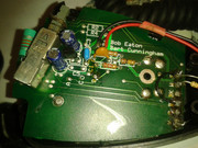
From your pic it looks like the mic element wires is. red wire circuit gnd /Green wire audio input to amp transistor. Get the schematic on cb tricks.com or astatic.com. gd luck .cheers n 73's
-
14CS06
- Top Poster
- Posts: 1796
- Joined: 04 Mar 2012, 09:15
- Location: JN33LN - ALPES-MARITIMES-06 France
Re: Astatic 575-M6 Teardrop.
Hellospeeddemon wrote: ↑20 Nov 2017, 20:20 From your pic it looks like the mic element wires is. red wire circuit gnd /Green wire audio input to amp transistor. Get the schematic on cb tricks.com or astatic.com. gd luck .cheers n 73's
The schematic is here
@+
Claude
Last edited by 14CS06 on 13 Apr 2018, 17:09, edited 1 time in total.
Photo Collector CB RADIO
-
Buick Mackane

- Moderator

- Posts: 9648
- Joined: 21 Aug 2012, 17:30
- Location: A citizen of legoland
Re: Astatic 575-M6 Teardrop.
From what i can see the green wire leaves the mic element and attaches to the top of the potentiometer
I Am the great cornholio are you threatening me ?
-
Tim
- Top Poster
- Posts: 1415
- Joined: 10 Jun 2016, 12:35
- Call Sign: 26AT239
- Location: Democratic Republic of Dartmoor
Re: Astatic 575-M6 Teardrop.
Please excuse my ignorance but where is the potentiometer and at what point on the board should the green wire be soldered? An arrow pointing to the point of attachment would be the most helpful.
-
JollyRoger

- Super Member

- Posts: 297
- Joined: 27 Apr 2011, 16:31
- Location: In The Shack
Re: Astatic 575-M6 Teardrop.
If im not wrong, any of the 2 points marked with yellow arrows, just DO NOT remove that red wire link when soldering it back in place
Regards JR
"Those who say it cannot be done shouldn't interrupt the people doing it"
"Those who say it cannot be done shouldn't interrupt the people doing it"
-
Tim
- Top Poster
- Posts: 1415
- Joined: 10 Jun 2016, 12:35
- Call Sign: 26AT239
- Location: Democratic Republic of Dartmoor
Re: Astatic 575-M6 Teardrop.
Thanks JR and everyone else that have replied, I'll give it a go.