SkyArrow 250
-
UGLY_BOB

- Legend

- Posts: 6159
- Joined: 09 Jan 2008, 10:15
- Location: Becalmed two days out of Cadiz !
Re: SkyArrow 250
So... have any of the boffins I mailed the schematic to come up with a 'clarifier' opening / K/c shift mod yet ? 

EXTREMELY WEIRD... AVOID AT ALL COSTS !

-
UGLY_BOB
- Legend
- Posts: 6159
- Joined: 09 Jan 2008, 10:15
- Location: Becalmed two days out of Cadiz !
Re: SkyArrow 250
Richard has forwarded me some notes and ideas on opening the clarifier...
You know the drill... If you want a copy, PM me an e-mail address... PM's won't support .pdf's .
Ugs
You know the drill... If you want a copy, PM me an e-mail address... PM's won't support .pdf's .
Ugs
EXTREMELY WEIRD... AVOID AT ALL COSTS !
-
Ashtec

- Legend
- Posts: 9156
- Joined: 30 Dec 2009, 23:12
- Call Sign: M6LTD
- Location: Uk
Re: SkyArrow 250
I was just thinking about this radio the other day bob has any one done the mod to the opening of clarifier so the radio can work on the uk frequences...........................

-
UGLY_BOB
- Legend
- Posts: 6159
- Joined: 09 Jan 2008, 10:15
- Location: Becalmed two days out of Cadiz !
Re: SkyArrow 250
Not yet... Tim was going to try it on his... but he's a busy man
I have to poke him with a stick to remind him every so often.
I have to poke him with a stick to remind him every so often.
EXTREMELY WEIRD... AVOID AT ALL COSTS !
-
Ashtec
- Legend
- Posts: 9156
- Joined: 30 Dec 2009, 23:12
- Call Sign: M6LTD
- Location: Uk
-
Ashtec
- Legend
- Posts: 9156
- Joined: 30 Dec 2009, 23:12
- Call Sign: M6LTD
- Location: Uk
Re: SkyArrow 250
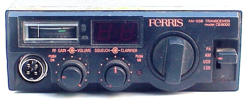
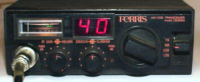
Here's aother radio that look's the same as the SkyArrow 250
Ferris - CB 8000
Ferris - CB 8000
-
Ashtec
- Legend
- Posts: 9156
- Joined: 30 Dec 2009, 23:12
- Call Sign: M6LTD
- Location: Uk
Re: SkyArrow 250
Can any one help us with the 'clarifier' opening / K/c shift mod....................
Ive been given information as you can see but i whant to know what you think on this as well before i get playing.......
Ive been given information as you can see but i whant to know what you think on this as well before i get playing.......
-
RD250
- Top Poster

- Posts: 1073
- Joined: 04 Dec 2010, 14:06
Re: SkyArrow 250
Hi Paul
I read the text above and there's couple of things that I don't fully agree with.
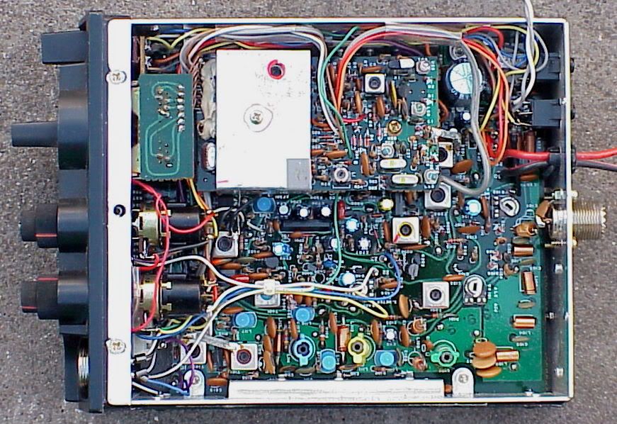
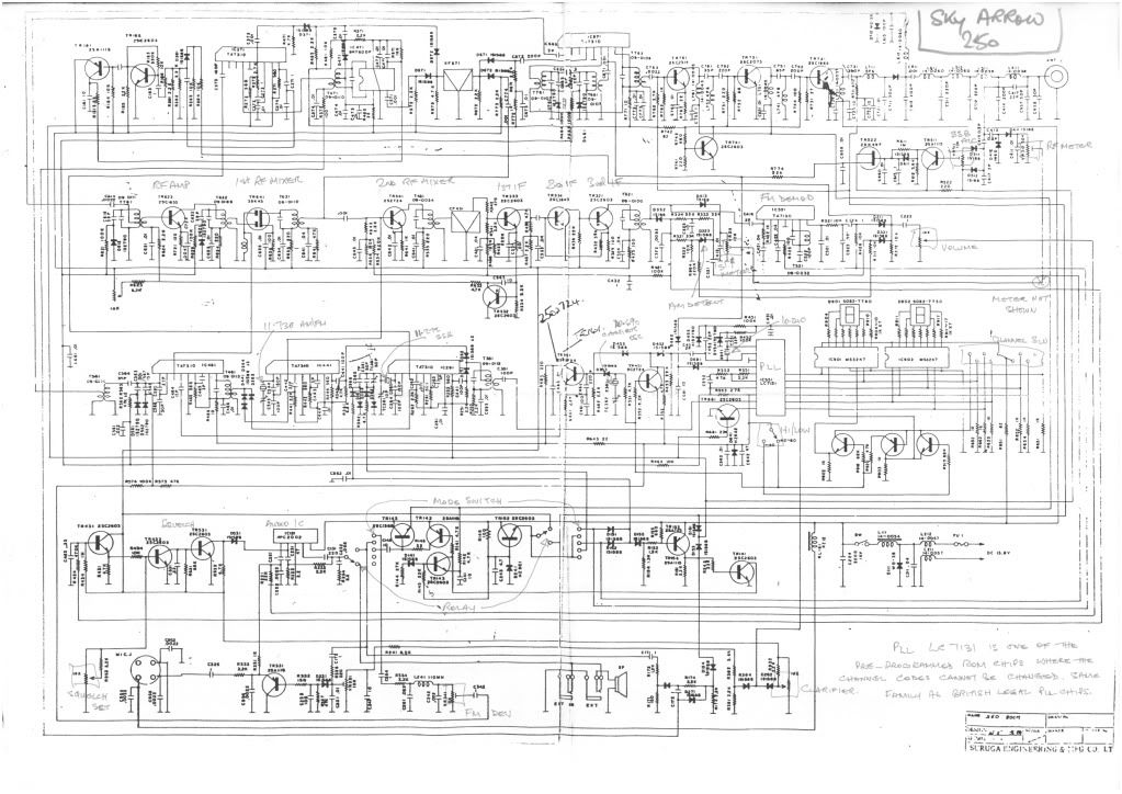
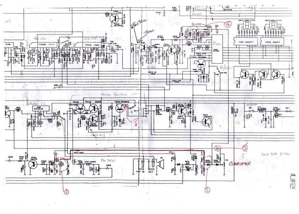
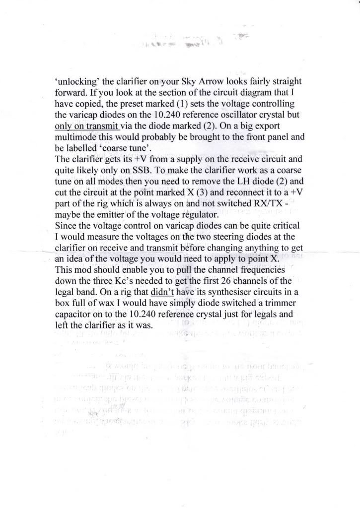
The trimpot highlighted as (1) sets a threshold for audio ALC on TX mode and has nothing to do with the clarifier.
The schematic readability is poor due to the quality of the copy but the clarifier voltage comes from the Rx arm of the relay (the relay switches the regulator output to either Tx only or Rx only circuits)
On Tx it simply connects to the Tx only side of the relay and uses fixed resistors to set the clarifier voltage. The back to back diodes marked as (2) provide isolation to stop the two sides pulling each other.
The clarifier is fed from the common Rx side of the relay so I expect the clarifier to work in AM/FM as well?
I agree with the basic instructions above as to how to mod/unlock it though. eg how to alter the circuit to unlock it but I don't think it will offer much tuning range.
Because the 10.24MHz oscillator xtal is connected up to the PLL chip it will use an unbuffered biased inverter inside the chip as the active part of the oscillator. Because the clarifier varactors simply alter the shunt capacitance on either side of this then I suspect you will get very limited control range. You could reduce the 22pF caps to get more range but this approach goes against common practice in how these oscillators are meant to be configured.
IMO the existing clarifier on the 10.24MHz PLL osc isn't a good place to start if you want a wide range unlocked clarifier. There is a better way to do this but it might be unrealistic as it would require a little piggy PCB inside the radio. However it would also offer the prospect of 120 channels (maybe more)
NOTE: The voltage regulator circuit looks very unforgiving of short circuits. I'd strongly advise precaution if probing around inside this radio with it switched on. One slight slip of a probe (we've all done this) could toast this regulator. In fact the device chosen appears to be a small NPN transistor. Maybe this is an error on the schematic? This device looks hopelessly underrated and over biased. Not a good regulator IMO.
If you do probe around inside this radio I'd advise running the PSU down at maybe 12V and also set a strict current limit. (that's what I would do)
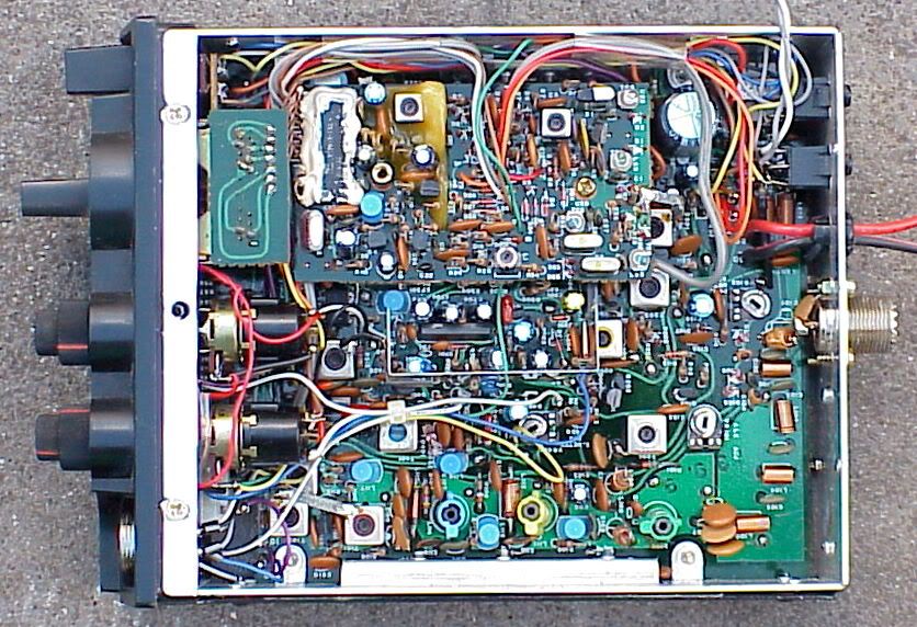
Can you check what transistor the real radio uses for the voltage regulator? This is the transistor (with 9V? zener) that is located a little below/right of the handwritten text "MODE SWITCH" in the schematic. I'd hope they have swapped this for something beefier...
I read the text above and there's couple of things that I don't fully agree with.
The trimpot highlighted as (1) sets a threshold for audio ALC on TX mode and has nothing to do with the clarifier.
The schematic readability is poor due to the quality of the copy but the clarifier voltage comes from the Rx arm of the relay (the relay switches the regulator output to either Tx only or Rx only circuits)
On Tx it simply connects to the Tx only side of the relay and uses fixed resistors to set the clarifier voltage. The back to back diodes marked as (2) provide isolation to stop the two sides pulling each other.
The clarifier is fed from the common Rx side of the relay so I expect the clarifier to work in AM/FM as well?
I agree with the basic instructions above as to how to mod/unlock it though. eg how to alter the circuit to unlock it but I don't think it will offer much tuning range.
Because the 10.24MHz oscillator xtal is connected up to the PLL chip it will use an unbuffered biased inverter inside the chip as the active part of the oscillator. Because the clarifier varactors simply alter the shunt capacitance on either side of this then I suspect you will get very limited control range. You could reduce the 22pF caps to get more range but this approach goes against common practice in how these oscillators are meant to be configured.
IMO the existing clarifier on the 10.24MHz PLL osc isn't a good place to start if you want a wide range unlocked clarifier. There is a better way to do this but it might be unrealistic as it would require a little piggy PCB inside the radio. However it would also offer the prospect of 120 channels (maybe more)
NOTE: The voltage regulator circuit looks very unforgiving of short circuits. I'd strongly advise precaution if probing around inside this radio with it switched on. One slight slip of a probe (we've all done this) could toast this regulator. In fact the device chosen appears to be a small NPN transistor. Maybe this is an error on the schematic? This device looks hopelessly underrated and over biased. Not a good regulator IMO.
If you do probe around inside this radio I'd advise running the PSU down at maybe 12V and also set a strict current limit. (that's what I would do)
Can you check what transistor the real radio uses for the voltage regulator? This is the transistor (with 9V? zener) that is located a little below/right of the handwritten text "MODE SWITCH" in the schematic. I'd hope they have swapped this for something beefier...
-
mattyboy
- Super Member

- Posts: 153
- Joined: 15 Jun 2008, 10:04
- Location: west yorkshire
Re: SkyArrow 250
here is mine what was ebay 
this radio looks like its never been used as all boxed packging and all that its mint it as all seals on as well its doing standed power 12 watts ssb 4/5 watts fm/am i put it on this morning and found that it would not transmit on highband but after 10mins warming up it came to life and works good audio a bit quiet and it bang on 12oclock as well...
this radio looks like its never been used as all boxed packging and all that its mint it as all seals on as well its doing standed power 12 watts ssb 4/5 watts fm/am i put it on this morning and found that it would not transmit on highband but after 10mins warming up it came to life and works good audio a bit quiet and it bang on 12oclock as well...
mass dx 5000 v4
cobra 148gtl-dx
stalker 9fdx
i-max- 2000 antenna
vector-4000 antenna x 2
wilson 2000 moble antenna

TM767 /26FB402 26WDC600
cobra 148gtl-dx
stalker 9fdx
i-max- 2000 antenna
vector-4000 antenna x 2
wilson 2000 moble antenna
TM767 /26FB402 26WDC600
-
UGLY_BOB
- Legend
- Posts: 6159
- Joined: 09 Jan 2008, 10:15
- Location: Becalmed two days out of Cadiz !
Re: SkyArrow 250
Matty... audio a bit quiet ? Do you mean TX or RX ? I found the standard mic was a bit of poo... but with a quality power-mic it was great.
Ugs
Ugs
EXTREMELY WEIRD... AVOID AT ALL COSTS !
-
mattyboy
- Super Member
- Posts: 153
- Joined: 15 Jun 2008, 10:04
- Location: west yorkshire
Re: SkyArrow 250
on tx but it sorted now 
mass dx 5000 v4
cobra 148gtl-dx
stalker 9fdx
i-max- 2000 antenna
vector-4000 antenna x 2
wilson 2000 moble antenna
TM767 /26FB402 26WDC600
cobra 148gtl-dx
stalker 9fdx
i-max- 2000 antenna
vector-4000 antenna x 2
wilson 2000 moble antenna
TM767 /26FB402 26WDC600
-
Ashtec
- Legend
- Posts: 9156
- Joined: 30 Dec 2009, 23:12
- Call Sign: M6LTD
- Location: Uk
Re: SkyArrow 250
Dose any one know what IF these radios are running on at all
-
smokescreen

- Super Member
- Posts: 139
- Joined: 20 Jul 2011, 18:49
- Location: Derbyshire
- Contact:
-
Ashtec
- Legend
- Posts: 9156
- Joined: 30 Dec 2009, 23:12
- Call Sign: M6LTD
- Location: Uk
Re: SkyArrow 250
I've not got one yet to get a look at the xtal filter i know were a few are.
-
smokescreen
- Super Member
- Posts: 139
- Joined: 20 Jul 2011, 18:49
- Location: Derbyshire
- Contact:
Re: SkyArrow 250
Sorry, I guessed you had one.
Well looking at the schematic, I will stick my neck out and say 11.275MHz 1st IF and 455KHz second...
The local osc for the 2nd mixer is 11.730MHz, - 455kHz = 11.275MHz and this matches up with the SSB osc
.
Well looking at the schematic, I will stick my neck out and say 11.275MHz 1st IF and 455KHz second...
The local osc for the 2nd mixer is 11.730MHz, - 455kHz = 11.275MHz and this matches up with the SSB osc
.